Tuesday, May 24, 2016

Pellet burner controller code


My pellet burner controller code become open source. The code is in programming language C. I post it at the GitHub: https://github.com/canji/Pellet-burner-controller

Comments in the code are on the Serbian. I don't have time now to translate it. If someone need help understand the code, please contact me

I have big omission in my previous post about pellet burner controller. Pellet burner expert which I cooperated is Miodrag Cvejin. Big thanks for him!

Tuesday, May 17, 2016

Diesel generators


Sometimes at my job I work with diesel electric generators. As a testing engineer I perform inspection and test of it. For testing we use a mobile load bank. Our mobile load bank is just resistive and it looks like giant heater. It has bank of heater and fan. Its maximum load is 1MW. 

Diesel generators aren’t complex machines. They have two parts. One is a diesel engine and second is an electric generator. 

From electrics and electronics stuffs a diesel engine has lots of sensors. The most typical is for an oil pressure and a temperature, a coolant level and a temperature and a pick-up for speed. 

A generator gives the sin wave output voltage with specified voltage amplitude and frequency. In our case this is always 400V between phases and 50Hz. 

The generator frequency depends from a diesel engine speed. We control frequency by controlling the diesel engine speed. Because most of generators are four pole electric machines we need 1500 rpm for frequency of 50Hz. 

Most of diesel generators that we test are older than me. This old diesel engines have fixed fuel injection. Because of this its frequency varies with changing a load. As we gain load the frequency goes down. Most of old diesel generators can take no more than 80% of load and for this load frequency goes down for 1Hz. 

New generation of diesel generators has an electric control fuel injection and them frequency is perfect 50Hz all the time. Just when we apply high jump of load the frequency changes a little. This change depends from a PID controller for speed control. When we apply high load, for example form 0% to 75%, frequency goes down because of suddenly high load. Depends of a PID controller it can be slow comeback to the 50Hz without over frequency or quick come back to the 50Hz with some peak of over frequency. 

For a generator voltage control a generator has voltage regulator. A generator is synchronous electrical machine and its output voltage depends from a magnetic field in a rotor. Voltage regulator is uses to control that magnetic field. It works as controlled AC DC converter. With DC voltage output it controls magnetic field in a rotor. 

Also as frequency, old diesel generators has fixed voltage regulator. Output voltage changes with changing frequency. In some case voltage goes down when frequency goes down and in some cases are oppositely. 

New generation of diesel generators has an electric controlled voltage regulator and output voltage is always perfect 400V. 

I reconstructed one voltage regulator and this interesting electronic story will be in the next post. 

Wednesday, May 11, 2016

Typical holiday

Adam and Milica

Last two weeks I was in the Brus. This is typical holiday for my family. The Brus is hometown of my wife Milica. This is a small town near Serbian famous mountain Kopaonik. There we always have a nice time.

My favorite sport activity is road bike climbing to the Kopaonik. There are four roads for climbing to the Kopaonik. I think every climb is the first category in cycling. I try every of four roads and my favorite climb is through “Kriva Reka” village. 

There are many interesting places near the Brus. Mountain Goc is also beautiful. Food is excellent there. In a future I will write more detailed about the Brus.

Top of Kopaonik mountain

Some pictures from previous holidays:  

My car preparing for the trip

Top of the hill above the Brus 

Bike climbing on the Kopaonik through "Kriva Reka" village

The old castle "Koznik" near the Brus


Monday, April 25, 2016

PH-PT click


I almost finish PH-PT click for the “MikroElektronika” company. This click board is interface for a PH electrode and a PT temperature probe. It contains two integrate circuits. One is the analog interface for a PH electrode and a PT probe LMP91200 and the second is analog-digital converter MCP3428. For communication with a microcontroller the PH-PT click board uses SPI for setting the analog interface LMP91200 and I2C for communication with the ADC MCP3428.

Reading PT probe is tested and it works fine. I’ll buy PH electrode and will test second functionality. 

I made a small mistake with voltage reference and I have to do a review. This would be just a little change in the PCB. There are too much administrative tasks at my job and my brain gets rusty. I must work more on a hardware and software.  

More about the “MikeoElektronika” click boards you can find on www.microe.com/click/.

Wednesday, April 20, 2016

KiCad

Pellet burner controller PCB in KiCad


KiCad is software for electronics design. The programs handle Schematic Capture and PCB Layout with Gerber output. 

KiCad is free software, open source. It runs on Windows, Linux and OS X. 

I like KiCad. I used it to design the Pellet burner controller PCB and plan use it for some future projects. 

KiCad is simple and comfortable to using and I recommend it to everyone. 

Saturday, April 9, 2016

Demand power


A demand power can be found at an electrical bill in an industry. Also, it can be found at an electrical bill in a household. In the industry the demand power is measured, and in a household this is just one more mysterious budget item at the electrical bill. 

An electric meter in the industry measures average power on the define time interval. The maximum average power on the define time interval in one month is demand power for that month. The define time interval can be from 10 minutes to 30 minutes. In Serbia this is 15 minutes. A new electric meter the 15 minutes interval synchronizes with a clock. 

If we in the industry take care about the demand power, we can have lower electrical bill. The goal is to have more uniformly electrical power consumption. If we have needs for peaks in electrical power consumption, we must arrange peaks in different 15 minutes time intervals. I have tried to investigate how to lower demand power at my job.


Wednesday, March 30, 2016

Linux is my biggest weakness


Sometimes I look job ads. I want to see what kind of engineer companies need. For many embedded software engineer job positions the Linux is necessary. Embedded Linux is most common operating system for embedded devices.

I have never worked with the Linux. Once I installed the Fedora Linux on my desktop PC but I didn’t use it a lot.

Now I plant to learn the Linux. I think this wouldn’t be hard. I will buy the Raspberry Pi Zero. This small computer for 5 dollars can be interesting base for many embedded projects. It has the Linux. I think the Linux on Raspberry Pi Zero would be too much robust for some real time embedded systems. I plan to investigate how this Linux distribution can be reduced and become more reliable for some embedded applications.


Some interesting sites and texts about Linux: 

Tuesday, March 22, 2016

Bike power meter

Fabian Cancellara

As the hardware and triathlon fan I am very interested in a bike power meters. There are lots types of bike power meters, but the principle of operation is similar. 

The equation for the bike power is: P = T * w. T is torque and w is angular velocity

The equation for torque is T = F * r. F is force and r is the distance from the center of rotation to the point where is the force applied. 

So the equation for the bike power is P = F * r * w. On a bike the force and angular velocity can be measured. The hardest part is the force measurement.

The strain gauge is using for measurement the force. This is insulating flexible backing which supports a metallic foil pattern. It is attached to the object by a suitable adhesive. As the object is deformed, the foil is deformed, causing its electrical resistance to change. This resistance change, usually measured using a Wheatstone bridge

The key of the bike power measurement is to put the strain gauges in some bike part. The strain gauges usually put in bottom bracket, rear freehub, crankset, or pedals. 

When the place of force measuring is known, r distance from the center of rotation to the point where is the force applied is easy to determine. For example, when strain gauges are put in the pedals crank length must be known (170mm, 172.5mm, 175mm, 177.5mmm…). 

If strain gauges are put in bottom bracket, crankset, or pedals w angular velocity is the same as the cadence (number of pedal revolution per minute). If strain gauges are put in rear freehub w angular velocity is the same as the bike wheel angular velocity. The cadence or the bike wheel angular velocity can be measured with magnet (measure the time of revolution) or with gyroscope

I was thinking about the bike power meter project. I was planning to put strain gauges in a bike shoes cleat. This would be interesting for Kickstarter, but someone was faster

Tuesday, March 15, 2016

How works power factor correction


I usually work with a low voltage capacitor banks for power factor correction. Then people ask me how it works? Lots of these people are from other professions and don’t have a knowledge of electrics. It is hard to explain it in a simple language with don’t using electric’s terms and formulas. 

Now I try to explain power factor correction for everyone, don’t depend from professions. 

This isn’t science text and don’t complain if I mix some basic physic terms.

The electric distribution system gives to us the electrical energy through AC voltage and current. In an industry we have two types of energy, one is active (kW), and other is reactive (kvar). Active electrical energy converts in other types of energy like heat, mechanical work, chemicals when charging batteries, light and other. Reactive energy used for creating and maintaining a magnetic field in electrical motors, inductive heaters, some kinds of lights and other. Reactive energy created and maintained a magnetic field on way that it takes energy from the electric distribution system and then returns it to the electric distribution system. This is reason why it calls reactive. Power factor presents ratio of active and reactive energy.

A capacitor needs just reactive energy for creating and maintaining electrical field. It is function just like magnetic field it terms of take and back energy from the electrical distribution system. One thing is different, the timing of take and back energy. When magnetic field take energy, electrical field would back energy and conversely. When we add a capacitor load reactive energy from magnetic field and reactive energy from electrical field added energy to each other and don’t take energy from electric distribution system. Consequence is low energy form the electrical distribution system, low main current, and low electrical power consumption bill. This is the way how works power factor correction. This is some kinds of paradox, we add capacitors, more loads to the electrical distribution system and electrical power consumption goes down.


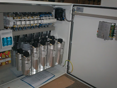
In industry we use low voltage capacitor banks in transformer stations. There is power factor regulator which power on or off capacitors depends of reactive power consumptions. 

If someone has better idea how to explain power factor correction, please contact me.

Sunday, March 6, 2016

Tempo calculator


When I was active runner, I had written a blog about distance running. Then, I was playing with web programming. For that blog I made tempo calculator using HTML and Java Script.

This calculator has data about time, distance and velocity. Distance and velocity data are shown in different units. The tempo calculator calculates one of three data from other two data.

Below is my tempo calculator. Interface is on the Serbian. If someone needs HTML, Java Scrip file, please contact me.


Tempo kalulator


Vreme
h min sek


Duzina
km m milje broj krugova na atletskoj stazi


Tempo
min/km min/milja km/h min/krugu na atletskoj stazi


Thursday, March 3, 2016

More efficiency induction motor


These days at my job there are talks about more efficiency induction electrical motor. Some people say that induction electrical motor can be different rewinding and then become a more efficiency. A little about induction motor:


Lots of people have made mistakes when talking about efficiency because they mention just power factor. Power factor isn’t always connects with efficiency. Nice text about it: 


A little more about power factor: https://en.wikipedia.org/wiki/Power_factor


One of new more efficiency winding is YY/D which explained in these two texts:


Sunday, February 28, 2016

Endurance is my hobby

Half-ironman, Belgrade 2014


Whole my life I am in a sport. When I was kid I trained karate. In elemental school I trained basketball. At high school sport was my second hobby. The first hobby was drumming. I was drummer in rock and heavy metal bends. During studding I was training long distance running in sport club Hermes. My coach was Bojan Maric

When I finished study and back to my hometown Zrenjanin I was continuing with running. Three years ago I tried triathlon. Triathlon is the most interesting hobby for me, but the most complex. In sport I like systematic, discipline and consistent training. This is very hard in triathlon in my case. I don’t have enough time. 

Now I am in sport’s “stand by”. I train a little just for fitness maintain. Last month I fell from a bike. I can’t extend my right arm. Last few years injuries have become problem. I have had problems with my hips and numb right foot during cycling. Now I also have problems with time. I am a fresh father and must do additional job. 

Because of many years in endurance sports I never give up. My best sport days will come. I am planning come back in systematic training. Is this will be running or triathlon depends of life resources. Until come back I am thinking about some adventures. I plan to ride bike from the Zrenjanin to the Brus, hometown of my wife Milica. There is the route about 280km. I plan to use some shortcuts which are go troughs very interesting countryside. I tried it once by a car. This would be one day adventure, from the sunrise to the sunset. If someone wants to join me on this please contact me.

Some of my personal bests:

5km - 16:55
10km - 35:29
half-marathon - 1:17:29
marathon - 2:52
half-ironman - 4:59
ironman – Hope one nice I will finish it. 

Sunday, February 21, 2016

Thermography


I use thermal camera very often at my job at the Petroleum Industry of Serbia. I use Fluke Ti55. This is excellent camera. Usually I have made thermal pictures of transformer stations, distribution boards, electric motors and pumps.


How thermal camera works?

Our eyes work by seeing contrast between objects that are illuminated by either the sun or another form of light. This is in the electromagnetic visible spectrum. In terms of frequency, this corresponds to a band in the vicinity of 430 – 770 THz.
Thermal cameras work is by “seeing” heat energy from objects. All matter with a temperature greater than absolute zero emits thermal radiation. Most of the thermal radiation emitted by objects near room temperature is infrared (300 GHz – 430 THz). Thermal camera creates images from infrared thermal radiation. 

Emissivity

Emissivity is a term describing the efficiency with which a material radiates infrared energy. Real-world objects have emissivity values between 0 and 1.00. An emissivity of 0.90 implies that the material is 90% efficient at radiating energy. An emissivity of 0.40 implies that the material radiates only 40% of that which it is capable of radiating.

More about emissivity can be finds here: http://www.optotherm.com/emiss-table.htm

More about thermography will be in future posts.

Sunday, February 14, 2016

Pellet burner contoller


Pellet burner controller is the most challenging project that I have worked on. This is the detail describe of it.

Some explanations before I start: 

  • Pellet fuels are heating fuels made from compressed biomass.
  • Pellet burner is burner which use pellet for fuel.
  • Pellet burner controller is an electronic used for manipulating pellet burners.


Pellet burner controller hardware description

On the next two pictures, picture 1 and 2 are represented the front and back of a pellet burner controller.

Picture 1. Front of pellet burner controller

 
Picture 2. Back of pellet burner controller


Parts of pellet burner controller from pictures 1 and 2:

  1. Easy TFT Board is 262K RGB colors display with touch panel, ideal for human-to-burner interface.
  2. Ethernet MCU card with LM3S9B95 microcontroller, which has a relatively important rolein the whole system.
  3. Digital input for photocell and thermostat, and analog input for NTC resistor. NTC resistor is reserved for measuring temperature.
  4. 230V AC input and AC output for burner’s fan, igniter and cleaner. The burner’s fan’s use is to insert air into the burner. The power of insertion must be precisely controlled and this is a serious real time purpose for the microcontroller. The burner’s fan is an AC one phase electromotor and it’s work is controlled by a triac. The microcontroller detects every time when a power sine wave goes through zero. When it comes through zero, the microcontroller starts the timer. When the timer stops counting down, the microcontroller sends an impulse to triac. The triac will give at that point a sufficient voltage to the burner’s fan. This is the way how the microcontroller hashes power sine wave, and controls the burner’s fan power. The zero cross interface circuit is my design. Every example of the circuit that I’ve found on the internet, at some point and some way didn’t worked properly. Between the microcontroller and triac is the optotriac. The igniter and cleaner also uses a triac. In those cases, there is used an optotriac with zero cross. The interface between the microcontroller, igniter and cleaner acts like a solid state relay. 
  5. 12V or 24V DC input and output for two feeders. Two feeders are a DC electromotor. The interface between the microcontroller and feeders are mosfet transistors and optocouplers. In that PCB region are place for solder interface for DC cleaner. This is a full bridge interface for the DC electromotor which can go forward and backward.
  6. 3.3V voltage regulator.
  7. The Ethernet Connector Board’s use is to connect the pellet burner controller and the PC. The pellet burner controller is working like a small web server. This is the most practical and effective way to connect the controller and the PC, no matter which operating system does the PC possess. Why should the user always have to go down to the basement for turning the pellet burner on and off? Now the user can control the burner directly from his PC, which eliminates the need for a person to actually be physically present by the burner, and excludes the act of directly interfering with the device. This function is now still under development. 
  8. USB connector for 5V power and update microcontroller software with help of USB bootloader.
  9. MikroBUS socket for GSM click. The user have an option to control the pellet burner with a simple SMS messages. This function is also still under development.
  10. Real time clock with battery.
  11. Connector for mikroProg for ARM.
  12. Input for temperature sensor DS18S20 and thermocouple. The DS18S20 can be used for measuring water temperature in the system or to measure the room temperature. The thermocouple’s use is to measure smoke temperature. The thermocouple interface is MAX31855K.


Pellet burner controller interface description

On the picture 3 are two options of the main display. The bought options have MENI button in upper left corner. The ‘Time and Date’ info is in the upper right corner. In the green area of the display is shown the burner’s work phase.The ‘T DIMA’ shows temperature of the output smoke. The ‘T AMBIJENTA’ info shows the system water temperature. The red button in the lower right corner is for turning the device on and off. On the left side of picture 3 is a display for an automatic workfucntion. There are two buttons for setting the goal system water temperature. On the right side of picture 3, the display for manual work is visible. There are five buttons available from P1 to P5 for adjusting the burner power. In this case P1 is the lowest power and P5 is the highest power. One note: interface is on Serbian.

Picture 3. Main display, left is automatic work, right manual work


Overall, the pellet burner controller has many functions. Since this document is a short and dense version of the whole concept and idea, additional details, finesses and further elaborations will not be shared on this occasion. Generally all the functions, modes and options will be described in the full version of the included user’s manual. For an additional info, there is something interesting that I would like to mention also; 

  • The Chrono-thermostat’s use is for programming the device when it’s automatic mode turns on/off or set to some certain power level. The Chrono-thermostat display is shown on the picture 4. An example from picture 4: the pellet burner will turn on every Monday at 1:30 AM manual work P1.
 
Picture 4. Chrono-thermostat display

  • The pellet burner controller has 42 parameters for adjusting operation. The parameters must be adjusted by a servicer, and regular user interference should be totally avoided and excluded in this scenario. For this reason, there is a password protection implemented. After a successfully and correct password entry, the servicer can adjust parameters as needed. Some of the parameter has a test function. The display for password and parameter adjustments is shown on picture 5.
 
Picture 5. Left is display for password, right is display for adjust parameters.

  • There are basic functions like adjust time/date and display calibration. The functions for language, adjust GSM and IP address are still under development. On picture 6 
  • are shown the ‘main menu’ and the ‘settings menu’.
 
Picture 6. On left side is main menu, on right side is settings menu.


Pellet burner controller first version

The first version of the pellet burner controller is working in a pellet factory for more than two years now. It’s embedded in a steel box case. The first version is much more simpler than the latest version. It has PIC microcontroller and 16x2 LCD display. On picture 7 and 8 is the first version of the pellet burner controller.
 
Picture 7. Front side of first version of pellet burner controller

 
Picture 8. Back side of first version of pellet burner controller

Tuesday, February 9, 2016

ECG click tested

I almost finish ECG  (electrocardiography) click for the “MikroElektronika” company.

More about the “MikeoElektronika” click boards you can find on www.microe.com/click/.

Thanks for the “MikroElektronika” company because they give me chance to show my possibility. 

The first test was success and the ECG click works fine. 

On pictures below are screens shots from ECG click testing. 

On the first picture is EasyMx PRO v7 for Stellaris ARM development board. The add-on board in the upper right corner is ECG click that I designed.


Thursday, February 4, 2016

Intelligent system for monitoring electrical power consumption

It was my Master’s Thesis and the first complex project that I have worked on. 
I presented it at the international conference “Eurobrand” in Kladovo in June 2011.

The first part of the system is power analyzer PM500, it is preview at the picture below.


PM500 measures 3-phase currents and voltages and calculates powers (S, P and Q), power factor, THD, maximum demand currents and powers and energy.

Intelligent system for monitoring electrical power consumption has the software for PC. With this software PM500 can be connect to PC. PM500 has RS485 connection port and for connection with PC we need RS485 to USB converter or RS485 to RS232 converter. Software for PC can read all data from PM500, draws it in real time and saves it in file. On pictures below there are screens shots from the software for PC.


Software for PC created in the Lab Windows CVI. 

Intelligent system for monitoring electrical power consumption has embedded system which can be connect to PM500. The embedded system reads data from PM500 and save it in a file at SD card. This file can be read and preview at PC in the previous described software for PC. 

The embedded system has the possibility of adding GSM module which informs users via SMS messages about electrical power consumption. 

Hardware for the embedded system used PICPLC16 v6 from “Mikroelektronika” company. It is preview on the picture below.


If you need more information about intelligent system for monitoring electrical power consumption please contact me.